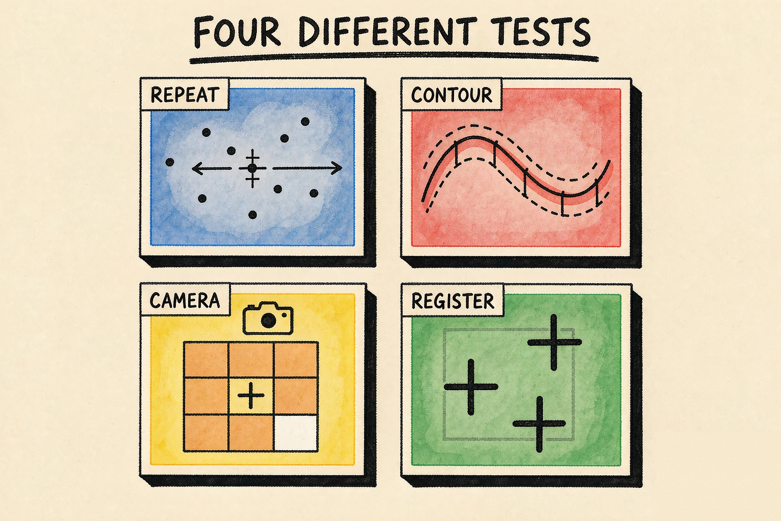
Four accuracy figures appear across the K8, L8, K10, L10 and G6 product pages: repeat positioning accuracy, contour accuracy, vision system resolution and registration at the marks. Each is measured differently, assumes different conditions and fails in a different way. Treating them as interchangeable is how buying decisions go wrong.
Factory calibration values, and how to use them
Every figure here is measured during factory calibration under controlled conditions and quoted consistently across our product pages and guides. Use them to compare configurations and capacity, then run your own material through the three-step check at the end of this page — a calibration value is a starting point, not a substitute for a cut in your own stock.
The four figures, and what each one actually measures
Each number answers a different question. Repeat positioning describes the motion chain, contour accuracy a short-stroke cut, vision resolution the camera, and registration the result at the printed marks. No single "accuracy" number covers all four.
| Metric | Value | What it measures | Measured under |
|---|---|---|---|
| Repeat positioning accuracy | ±0.02 mm | Spread of head return positions at the same commanded point — single axis, full stroke, bidirectional | Defined in the first subsection below |
| Contour (processing) accuracy | ±0.01 mm | Deviation of the cut contour from its programmed toolpath on short-stroke cuts, without vision correction | Defined in the second subsection below |
| Vision system resolution | 0.025 mm/px | Pixel pitch of the industrial registration camera — the smallest increment the system can address | Defined in the third subsection below |
| Registration at marks | 0.025 mm | Residual misalignment between cut line and printed graphic at the registration marks, after whole-sheet alignment | Defined in the third subsection below |
Repeat positioning accuracy: ±0.02 mm
This is the mechanical floor of the whole system. The head returns to the same commanded point along a single axis, traveling the full stroke in both directions; the figure describes the spread of those return positions, not the best of them. Because it absorbs everything in the motion chain — rack and pinion wear, guide way alignment, servo response, thermal growth over a long shift — it is the coarsest of the four numbers. A machine's repeatability is what your tenth job of the day inherits from your first.
Plan around ±0.02 mm as the envelope the machine holds across its full travel, not as a best-case number from a single favorable run. Sample material, cut depth and ambient temperature all shift the result, so record those conditions when you run the check below.
Contour accuracy: ±0.01 mm
Contour accuracy describes how far the cut line can deviate from the programmed toolpath on short-stroke contours, measured without vision correction so that the result isolates the cutting system itself. The figure is smaller than repeat positioning for a mechanical reason, not a marketing one: a short stroke does not accumulate full-travel error. The head is never asked to find a point at the far end of the table — only to follow a contour a few hundred millimeters across, where the same motion chain has far less room to drift.
The most common misreading of this figure is treating it as a whole-table position guarantee. It is not that. If your work depends on features landing in the same place across an entire sheet, the figures that matter to you are repeat positioning and registration — not contour accuracy alone. Substrate, tool, contour size, cut depth and sample count all need to be fixed before a contour figure means anything.
Vision resolution and registration: one system, two fields
The 0.025 mm figure appears twice in our specifications because it is one system described by two fields, not two independent measurements. The industrial registration camera resolves 0.025 mm per pixel, and that pixel pitch is also the smallest registration increment the system can act on. Quoted as a registration figure, 0.025 mm is one pixel — a conservative bound rather than a physical limit, since the true quantization error is half a pixel on each side.
Registration works as a whole-sheet correction, not a continuous one: the camera reads the printed marks, the system computes the offset and rotation between the cut file and the actual printed sheet, and the toolpath is compensated once. The figure therefore applies at the registration marks. Across a full sheet, the residual misalignment depends on the print's own registration accuracy and the dimensional stability of the substrate, and it is normally larger than the figure at the marks — on a stretched or humidity-swollen substrate, noticeably larger. Camera field of view, mark type and sub-pixel interpolation all affect the result, so fix them before comparing readings.
For the full vision workflow, see our guide to CCD vision registration.
The machine elements behind the figures
Specifications are downstream of hardware, so the hardware deserves a sentence of its own. Positioning behavior rests on a ground rack-and-pinion drive and linear guide ways; the vacuum hold-down — a 7.5 kW air-cooled vacuum pump on the models discussed here — keeps thin stock flat, which matters because a sheet that lifts or shifts under the knife makes every accuracy figure on this page irrelevant at once. Oscillating tools run at high frequency on a selectable stroke, which is what keeps thick or fibrous materials cutting cleanly instead of tearing. Both are set per material rather than quoted as a single figure, because a frequency that gives a clean edge in foam tears a laminated board.
Reading a specification sheet
Three conditions decide whether an accuracy figure can be compared at all: what was measured, under which conditions, and on which machine. Ask for the sample material, cut depth, sample count and ambient temperature behind a repeatability or contour figure; for a vision figure, ask for camera field of view, mark type and whether sub-pixel interpolation is used. A number without its measurement conditions cannot be compared with another vendor's number — including with our own.
Oscillation frequency and stroke are set per material rather than quoted as fixed specifications, because a frequency that gives a clean edge in foam tears a laminated board. Traverse speed is likewise not production throughput: cut quality at production speed is what pays for the machine.
Compare our figures against our own figures, and against a competitor's only when both were taken on the same file, material and procedure. For your own job, the sample cut below settles more than any table.
Four limits worth knowing
- 0.025 mm registration applies at the marks. Across the full sheet, print registration and substrate stability take over, and they are outside the machine's control.
- ±0.01 mm is short-stroke contour deviation, not a whole-table positioning guarantee.
- Figures from different vendors are not directly comparable unless both were taken on the same test file, material and procedure.
- Idle traverse speed is not production throughput. Traverse speed sells machines; cut quality at production speed pays for them.
How to check the figures on your own material
You do not need our cooperation to test most of this page. Three steps, one afternoon:
1. Cut five identical square contours from the same file, at the same position on the sheet, in your production material, with the tool you actually use. A 100 mm square is a practical size. Record the material, tool, cutting depth, and sheet temperature — without these, the measurement has no context. 2. Measure each contour with a caliper or optical measuring device. Record the actual dimensions and position against the programmed path, and keep the largest deviation. This is your contour-accuracy reality check. 3. Repeat step one near the far corner of the table. The difference between center and far-corner deviation is the number that decides whether your full-size work comes out consistent — record it alongside the other two.
If you would rather see the test run on our floor, send us your material and file; we cut sample pieces and return results within 24 to 48 hours.
Where this shows up on the production floor
On printed graphics, registration is the difference between a sellable sheet and scrap: a compensated cut stays inside the artwork's tolerance at the marks, while an uncompensated one drifts visibly by the far edge — most expensively on the last sheet of a long run, when material cost and deadline pressure are stacked against a reprint. On prototype and short-run work, the pair that matters is contour accuracy and repeatability: whether the tenth unit cut today matches the first, without a test cut in between. And on thin or flexible stock, everything above is downstream of hold-down — if the pump and table cannot keep the sheet still, no camera or servo spec rescues the job.
Related pages
- K8 digital flatbed cutter — the sampling and short-run configuration
- CCD vision registration guide — how the vision system reads and corrects
- Full product line — all five models and their configurations
- Frequently asked questions — materials, files, and ordering