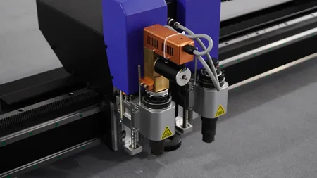
Ask how thick a digital cutting machine can cut and the answer arrives as a range: 0.1 mm to 50 mm. It is a true statement and a misleading one. No single tool head spans it. The figure is the union of five different heads, each with its own ceiling, and the ceiling is almost never the material — it is the blade.
That distinction matters the moment a job lands outside the comfortable middle. A buyer comparing machines on the headline range will specify a configuration that cannot cut the board in front of them, or pay for a head they never needed. The limit is mechanical, and it is predictable once you know which part of the tool runs out first.
This guide takes the thickness axis on its own. It does not repeat the material-to-head matrix — that lives in the tool head reference and the material compatibility guide. It answers what sets the floor, what sets the ceiling, why the two are unrelated, and what to measure before you sign a specification.
Key Takeaways
- "0.1–50 mm" is the union of five tool heads, not the stroke of one machine.
- The ceiling is set by how much blade is exposed, not by how long the blade is.
- The shortest blade that reaches through the material is usually the most accurate one.
- The floor is a different problem: below a certain thickness the material stops holding itself, and bending stiffness falls with the cube of thickness.
- Nominal thickness is not what the blade meets. Vacuum compresses soft stock, and depth must be set on the compressed figure.
Quick Answer
A digital flatbed cutter covers roughly 0.1 mm to 50 mm, but only through interchangeable heads: the drag knife handles 0.1–3 mm, the oscillating knife up to 50 mm, the V-cut tool 3–50 mm. The ceiling is set by blade overhang — the further a blade is exposed the more it deflects — and the floor is set by the material's own bending stiffness, which falls with the cube of thickness.
Why 0.1–50 mm Is Not One Number
The five heads share one carriage, one gantry, and one vacuum bed. What they do not share is reach. Each is a different mechanism with a different relationship to the material: the oscillating knife vibrates vertically and saws, the drag knife trails a free-swivelling blade and slices, the creasing wheel presses a fold line without severing, the kiss-cut blade stops inside a laminate at the liner interface, and the V-cut tool mills a groove at a fixed angle. Four failure modes at the extremes, not one.
So a specification of 0.1–50 mm describes a platform with the full head set, not the machine on the quote sheet. Two consequences follow. The low end belongs almost entirely to the drag knife, so for a 30 mm foam job the usable range starts wherever the oscillating knife becomes stable — the 0.1 mm figure is irrelevant. And a machine quoted with fewer heads has a narrower real range even though the platform number is identical, which is how two quotes for the "same" 50 mm machine can differ by a factor of two and both be honest.
The Upper Limit Is Blade Overhang, Not Blade Length
A cutting blade behaves like a cantilever. The portion gripped in the holder is fixed; the portion extending past the blade guide is a free beam hanging in space, and a beam loaded sideways at its tip bends. Cutting resistance is exactly that sideways load, applied continuously along the exposed length.
The failure signature is specific. The rigid upper part follows the programmed path; the tip lags behind the direction of travel and drifts. The cut is then not in the wrong place — it is at the wrong angle. Edges come out tapered rather than vertical, curves flatten, and parts measure oversize on the bottom face while the top face measures correct. Operators who measure only at the top surface will pass the job.
Blade length matters only through overhang. A long blade held short has short overhang and behaves like a short blade. The variable governing precision is the distance from guide to tip, so the correct setup is the minimum exposure that still reaches through the stock and just barely into the mat. That is the origin of a rule that runs against buying instinct: the shortest blade that can safely cut through the material is usually the most accurate one. Longer blades exist to reach deeper, not to cut better.
The industry guidance is numerical. Choose a blade at least 5 mm longer than the material thickness — no more — with common blade lengths running 10–45 mm and specialized blades beyond 100 mm only for block foam and similar deep work. Blade thickness is the second lever: common stock is 0.63 mm, 1.0 mm, and 1.5 mm, and rigidity scales with the cube of thickness as it does for any beam. Both levers trade identically — stability bought at the cost of reach or detail.
The blade catalogue holds hard evidence. Take two oscillating blades from the same manufacturer: one has an overall length of 36 mm and a maximum cutting depth of 5–6 mm, most of it shank, and that short exposed section is exactly why it outlasts longer blades in dense rubber and gasket stock. The other cuts to 15 mm, and the manufacturer's own note says the longer blade is prone to lateral deformation and chipping in hard material. Overall length and cutting depth are not the same quantity, and the deeper-cutting blade is the weaker one. A spec sheet listing only blade length tells you almost nothing about what it will cut.
Thickness by Tool Head — and the Two Heads That Do Not Fit the Table
Assembling five heads into one thickness table runs into an immediate problem: three have a working range in millimetres and two do not. Reporting the two without a range looks like missing data. It is not — it is a category difference, and flattening it into a millimetre column would be the error.
| Tool head | Working thickness | What sets the limit | Measured in mm? |
|---|---|---|---|
| EOT — oscillating knife | up to 50 mm | Blade overhang and side load; foam and corrugated forgive far more than dense board at the same thickness | Yes |
| DCT — drag knife | 0.1–3 mm | Blade offset and the side force generated at each turn, not blade reach | Yes |
| VCT — V-cut tool | 3–50 mm | Groove depth needed to fold, which follows the board rather than the blade | Yes |
| CCT — creasing tool | Not stated in mm | A pressure wheel forms a fold line and never enters the material, so there is no depth to reach | No — graded by board weight and fold quality |
| KCT — kiss-cut tool | Not stated in mm | Depth is a three-layer budget: face plus adhesive must be severed, liner must survive | No — graded by the liner, not the total thickness |
Creasing is the clearest case for keeping the categories apart. Its job is to crush a line into the board so the fold lands where the designer intended, and the board never separates. Asking what thickness it cuts is the wrong question; the right one is what board weights it creases without cracking the coating. A 600 gsm grey board and a 300 gsm folding carton are both "one sheet" and both crease, at settings that have nothing to do with a millimetre figure.
Kiss cutting is subtler because it does involve a millimetre depth — just not the depth of the material. The blade must pass through the printed face and the adhesive and stop at the liner, so the governing dimension is the liner caliper underneath, not the stack above: 23–50 µm on PET, 50–75 µm on glassine. A job described as "0.5 mm label stock" tells you nothing usable about the depth setting. The kiss cutting technique guide works that budget in full.
The practical reading of the platform's 0.1–50 mm is therefore: 0.1–3 mm goes to the drag knife; 3–50 mm splits between oscillating knife and V-cut tool depending on whether the part needs a fold; creasing and kiss cutting ride alongside on their own scales.
The Lower Limit Is a Different Problem: Thin Stock Cannot Hold Itself
Cutting thick material is hard because the blade must get all the way through without burning, breaking, or leaning. Cutting thin material is hard for the opposite reason: the blade is through almost immediately, and everything after that is a fight to keep the material where it was put. The difficulty does not shrink as stock gets thinner. It changes shape.
The governing property is bending stiffness, and it scales with the cube of thickness. Halve the thickness and the sheet does not become twice as floppy — it becomes eight times as floppy. This is why the drop from 0.5 mm to 0.1 mm is not a smooth continuation of the same job, and why a vacuum setting that holds a 0.5 mm sheet will not hold a 0.1 mm one.
Four distinct problems appear at that end of the range, routinely mistaken for one another because they all present as a bad edge or a bad part. They have different causes and different fixes, which is why no single troubleshooting move clears all four.
| Symptom | What you see | Cause | Correct fix |
|---|---|---|---|
| Wrinkling | Material bunches ahead of the blade, edge wanders | The sheet is not fully flattened, so material is pushed rather than severed | Full-area vacuum hold-down; reduce feed rate |
| Lifting with the blade | Part rides up on the upstroke or vanishes under the knife | Holding force too low to overcome blade adhesion and friction | Increase vacuum; review blade type and entry depth |
| Static cling | Small parts stick to each other or to the bed | Friction charging on thin film | Control humidity; change how parts are picked |
| Distortion on pick-up | Part is cut correctly then stretches when removed | The part is too floppy to lift without tearing | Layout with tie points, or switch to a kiss cut and leave it on the liner |
The last row is the one worth carrying into a quote conversation. When a part is too floppy to handle, the answer is usually not a better machine — it is to stop freeing the part. A kiss cut leaves every piece on the carrier sheet, solving handling at the source. That costs nothing to specify in advance and a scrapped run to discover afterwards.
What sets the floor at 0.1 mm is neither control resolution nor the accuracy figure in the brochure. It is the point past which the material can no longer be held flat and severed predictably — and past which a blade edge, which always carries a small rounding radius, begins pushing material aside instead of slicing it. Hence a rule that trips up distributors regularly: the 0.1 mm figure is a material-thickness floor, not an accuracy specification. It describes how thin a sheet can be processed, not how closely the machine holds a dimension.
Nominal Thickness vs. What the Blade Actually Meets
Every thickness figure on a specification is a relaxed thickness, measured with the sheet lying free on a bench. On the bed it is a different number, because the vacuum that holds the material down also squeezes it.
Soft and porous stock compresses most. A foam board measuring 10 mm on the bench can sit noticeably thinner under full vacuum, and the blade must be set for the compressed height. Set depth from the bench figure and the tip stops short of the mat, leaving bottom fibres connected; overshoot and it drives into the mat, blunting the tip. Neither failure looks like a depth error on the finished part — one reads as a bad blade, the other as a worn mat.
Porosity cuts both ways. Open-cell foam and non-woven material pass air, so vacuum loses grip through the sheet itself and the stock may compress unevenly, tilting under the tool. Dense sheet such as acrylic seals well and holds hard but barely compresses, which means depth control has to come from the machine rather than from the material yielding.
The rule is to measure on the bed, under vacuum, along the cut path — not on the bench and not at the sheet corner — then add a small allowance rather than a large one. An excessive margin drives the blade into the sacrificial mat on every pass, which is how a mat that should last months is cut through in weeks. The same reasoning explains a phrase that sounds like marketing and is actually a warning: maximum cutting thickness is what the head reaches in ideal stock; practical cutting thickness is what it reaches in this stock, at this density, under this vacuum, and it is always the smaller number.
When the Job Exceeds the Head
Thickness above the working range is not a dead end, but the three ways out have very different cost structures, and choosing between them is a production decision rather than a purchasing one.
Change the head. Cheapest and fastest when another head already covers the range. A 4 mm rigid PVC part that a drag knife cannot manage is routine work for the oscillating knife or the spindle on the G6, and changeover is minutes. This is the entire argument for a modular carriage: the machine already does the job once the right head is in it.
Take multiple passes. The standard answer for thick or dense stock that one deep pass cannot clear. Each pass removes less material, keeping blade load inside what the blade can take without deflecting. The cost is time, and time on thick stock is not linear — a second pass roughly doubles cycle time and adds a second chance at registration error. It works, and it is the wrong choice at volume.
Change the process. Past a certain thickness the material stops being a knife job. Solid wood, MDF, thick aluminium and dense composites belong to a router; deep foam blocks to a long-blade machine built for block work; double-wall corrugated at volume to a die. A flatbed knife cutter is the right answer for the overwhelming majority of signage, packaging, and display work and not for everything — saying so early is what keeps a specification honest.
One related case looks like a thickness problem and is not. When the part must fold rather than separate, the constraint is groove geometry and it follows the board construction, not the caliper: a 10 mm honeycomb panel and a 10 mm solid foam board are the same thickness and completely different V-grooving jobs, because one has cells to open and the other a continuous skin. The honeycomb V-grooving guide covers that case.
How Thickness Interacts With Accuracy
Accuracy does not improve or degrade steadily across the range. It is worst at both ends for opposite reasons and best in the middle, and knowing which end you are on tells you which correction to apply.
On thin stock the error comes from the material moving. The blade may be exactly where the program put it, but the sheet shifted a tenth of a millimetre between the vacuum settling and the cut arriving, so the part is wrong in a way no calibration fixes. Reducing feed rate and improving hold-down address it; checking the machine's accuracy specification does not. On thick stock the error comes from the blade leaning: the sheet is immovable and the tool is the flexible element, so the top face measures true and the bottom oversized. The correction is shorter overhang, a thicker blade, or a different head — again, not a calibration adjustment.
In the middle of the range, with the right head and a blade exposed just enough, the machine's own numbers become the useful ones: ±0.01 mm processing accuracy, ±0.02 mm repeat positioning, and a CCD camera at 0.025 mm resolution for print-to-cut registration. These describe machine capability, and they hold only while the material and the tool are behaving — which is the part a specification sheet leaves to the reader.
What to Measure Before You Specify a Machine
Five measurements settle most of the thickness question before any money moves.
- Thickness on the bed, under vacuum. Not the bench figure. This is the number the blade meets.
- Variation across one sheet. Local thickness variation is common in foam and recycled board, and it sets the allowance you must carry.
- Density, not just thickness. A 20 mm foam and a 20 mm acrylic are two different jobs with two different heads.
- Whether the part must separate or fold. This decides between knife and V-cut before any thickness discussion, and whether creasing enters at all.
- What the part must survive after cutting. Too floppy to pick up means a kiss cut on the liner may be the answer, not a through cut with tie points.
Then apply the rule that resolves the headline range: read 0.1–50 mm as a platform figure and ask which heads are in the quote. A K8 or L8 set up for sample and short-run work will not carry the same head set as an L10 or K10 configured for automation and volume, and the real thickness range follows the heads rather than the model number. Get the head list right and thickness stops being a range and becomes a number for your material.
Frequently Asked Questions
How thick can a digital cutting machine cut?
Roughly 0.1 mm to 50 mm, but that range is the union of five interchangeable heads rather than one machine's stroke. The drag knife covers 0.1–3 mm, the oscillating knife up to 50 mm, and the V-cut tool 3–50 mm. Creasing and kiss cutting are measured on different scales entirely. What a specific machine cuts depends on which heads come with it.
What limits the maximum cutting thickness?
Blade overhang. The exposed portion of a blade is a cantilever, and side load during cutting bends it, so the tip drifts away from the programmed path while the supported upper section stays true. The result is a tapered edge and an oversize bottom face. Blade length matters only through how much of it is exposed — a long blade held short behaves like a short blade.
Why is the minimum thickness 0.1 mm instead of zero?
Because below a certain caliper the material cannot be held flat and severed predictably. Bending stiffness falls with the cube of thickness, so a sheet at half the thickness is eight times as floppy, and a blade edge with any rounding radius begins pushing material aside rather than slicing it. That figure describes a material floor, not a dimensional tolerance.
Can a drag knife cut 5 mm material?
Not well, and the obstacle is not blade reach. A drag knife steers by trailing a free-swivelling blade behind the tool centre, with an offset of roughly 0.25 mm between tip and pivot, and it generates side force through every turn. Thicker stock reduces the effective offset and raises that force, so corners round off and edges tear. Cutters built for deeper work use a larger offset, buying depth at the cost of a much larger minimum corner radius.
Does the datasheet thickness match what the machine will cut?
Not exactly. Datasheet figures are relaxed thickness measured on a bench; on the bed the vacuum compresses soft stock, so the blade meets a thinner sheet. Depth must be set from the compressed height measured under vacuum. Maximum cutting thickness is what the head reaches in ideal stock — practical cutting thickness in your stock is always the smaller number.
What if my material is thicker than the machine's range?
Three options in ascending cost: change to a head that covers the range, take multiple passes at a shallower depth each, or move the job to a different process such as routing, a long-blade block machine, or a die. Multiple passes work but scale badly, since a second pass roughly doubles cycle time. Past a certain thickness the material is simply not a knife job.