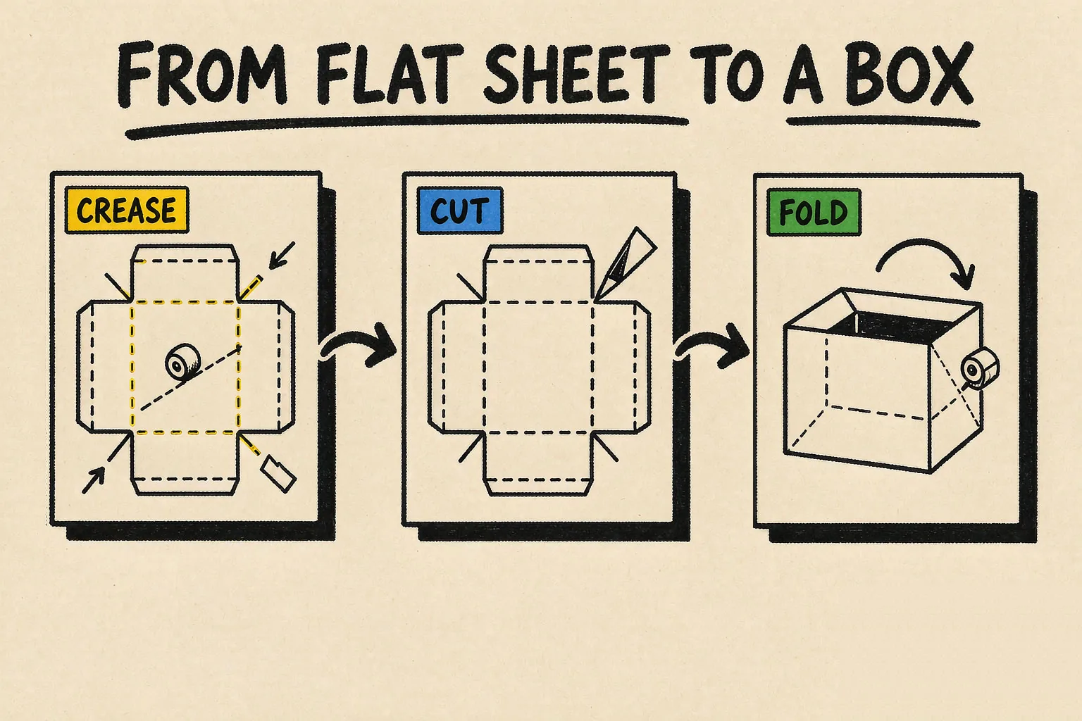
A packaging prototype is not a drawing of a box. It is a box that has been filled, closed, and opened by someone who did not design it, and it exists to find the faults that no screen will show. The faults are physical: a tuck flap that springs open, a crease that cracks on the second fold, a panel that measures correctly and still will not close because the board is 0.4 mm thicker than the model assumed.
That is why prototyping on a flatbed cutter is a different activity from production cutting. The objective in production is throughput. The objective in prototyping is iteration speed and dimensional truth, which puts the requirements in a different order.
Why the sample is the specification
A CAD model of a folding carton carries a board thickness as a number. Real board varies within a coil, and the variation is often larger than the clearance designed into the lock. A prototype cut from the actual production board exposes that in ten minutes. A prototype cut from a nominal-thickness substitute does not.
The same applies to crease behavior. Crease width, board thickness, and coating interact, and the result differs between two suppliers of nominally identical stock. A sample cut and folded on the real material is the only reliable way to set the crease, which is why the first sample from a new material is always a settings test as much as a design test.
The six steps
The workflow below assumes a cutter with an oscillating knife and a creasing head, which is the minimum configuration for structural packaging work.
Step one — clean the file. The die-line must be closed, on one layer, at 1:1 in millimeters, with crease lines on a separate layer from cut lines. Most bad first samples are a file problem: open contours that the software closes with a straight line, or a drawing exported at 0.1 scale. Cut and crease must be distinguishable by the machine, not by the operator's memory.
Step two — set the tooling. Cut with EOT on corrugated and heavier board, DCT on thin carton where edge finish matters. Crease with CCT. If the structure has a fold that must form a sharp corner — display bases, some rigid box corners — the fold line becomes a V-groove and VCT cuts it. Head changes are tool-free and take under three minutes on LDCUT machines, so a mixed structure with both a crease and a V-groove is one setup, not two.
Step three — set depth against the material. Depth is referenced to the material surface, not to the bed. On the 10 models the dual infrared tool setter does this automatically after a head change; on the 8 models the depth is set manually and should be re-checked after every head change. This is the step where a machine saves or costs the most time in a prototyping shop, because prototypes mean frequent head changes.
Step four — crease, cut, and strip. Run the sheet, then strip the waste by hand. If waste does not lift cleanly the cut is incomplete somewhere, and a sample assembled from a partially cut blank will teach you the wrong lesson about the fit.
Step five — assemble and load. Fold, glue, and fill with the actual product or a weight-matched substitute. Filling is not optional: a box that looks correct empty and bulges when loaded has failed, and the failure only appears under load.
Step six — measure and record. Record the crease width, depth setting, material batch, and the two or three dimensions that matter for fit. That record is the only thing that makes the next iteration faster than this one.
Three structures and their tooling
The three families below cover most packaging prototyping work. They differ in tooling and in the parameter that decides success.
| Structure | Typical board | Cut | Fold | The parameter that decides success |
|---|---|---|---|---|
| 0201 slotted carton (RSC) | Corrugated, single or double wall | EOT | CCT on the score lines, or no crease on a simple RSC | Flute direction against the fold. Creasing across the flute cracks the liner |
| Tuck-top / tuck-bottom carton | Folding carton board, 250–400 gsm | DCT for edge finish | CCT | Crease width against board thickness. A wrong setting shows at the fold line before it shows anywhere else |
| Rigid box (set-up box) | Grey board wrapped with printed paper | EOT on grey board | VCT for the corner grooves, CCT for the wrap creases | Groove depth against grey board thickness. The wrap hides a groove that is 0.2 mm wrong, and shows it at the corners |
The RSC looks like the easy case and is not. Corrugated resists creasing because the flute is a void: the crease wheel crushes the flute on one side and the board springs back on the other. Cutting a score rather than creasing it, or creasing along the flute rather than across it, changes how the box behaves when stacked. For blank layout and flute direction, see the corrugated box cutting guide.
The rigid box is the case where a knife machine and a V-cutter together replace a specialist corner-cutting step. VCT cuts the V-channel that lets the grey board fold into a 90-degree corner without a visible seam, and the wrap tolerance is set by that groove rather than by the operator's hand.
What this workflow needs from a machine
Prototyping puts unusual demands on a cutter, and they are not the demands production puts on it.
Frequent head changes. A prototyping shop switches between cutting, creasing, and grooving several times a day. That makes the tool setter the most valuable option on the machine, and it is the honest reason to choose a K10 or L10 over a K8 or L8 in a prototype environment, despite the identical cut specification.
Small, varied sheets. Prototypes are cut from offcuts and sample sheets, not from full production pallets. On LDCUT knife models the rolling felt conveyor table with zonal vacuum hold-down lets the zones be switched to match small sheets, so a 400×300 mm blank is not held by a vacuum field designed for 1600×2500 mm.
Tolerance to odd material. Prototype work attracts materials the production floor never sees: a new coated board, a recycled stock, a laminated sheet. Every one of them needs a test cut before the design is judged, because the material changes the crease and the depth.
Registration on printed wrap. For rigid boxes the wrap is printed before it is applied, and it must align to the board beneath. The camera is standard on all five LDCUT models at 0.025 mm resolution, giving 0.025 mm registration at the marks — with the caveat that the figure holds at the marks and grows toward the far edge as printed stock stretches. On a wrap that has been printed and left to settle, that difference is worth measuring before a run.
Quoting: per piece or per hour
Prototype work is usually quoted one of two ways, and the choice changes the customer conversation.
Per piece suits a defined sample quantity from a fixed file: ten boxes, one design, one material. The price is dominated by setup, not by cutting time, which is why the tenth sample costs a fraction of the first.
Per hour suits development work where the design is still moving: an unknown number of iterations on an unknown number of materials. The customer buys access to the machine and the operator's judgement for a block of time.
The mistake in both cases is quoting cutting time as if it scales with area. It does not. Cutting time scales with total path length, and a small box with a decorative die-line can carry more path than a large plain shipper. This is the same arithmetic used in choosing a packaging cutter, where the estimate is machine cutting speed divided by path length per sheet.
For a digital cutter the honest statement about cost is that the machine removes the die, not the labour. Someone still sets depth, strips waste, folds, and glues. What changes is the order threshold: a run of twelve stops being an uneconomic nuisance.
Where this process is the wrong choice
Digital prototyping is not the right answer for every packaging question, and the boundaries are mechanical rather than commercial.
If the design will never change and the volume is high, a steel-rule die and a platen press beat any knife machine on per-piece cost. Prototyping on a cutter is a step you take before that decision, not instead of it.
If the structure needs a wall thicker than the head can reach in one pass, the process is not a knife process. Rigid PVC and acrylic components — blister cavities, POS hardware, display brackets — need a spindle, which on LDCUT machines means the G6 digital flatbed cutter.
If the requirement is a soft-tooling sample in a material the machine has never been tested on, the first cut is a material test, and it should be treated as one: a single blank, measured, before a design is committed.
Related pages
- Packaging cutter selection — the five-question decision table
- Digital flatbed cutter range — specifications for all five models
- Material compatibility guide — material against head
- Applications overview — the other seven application areas
- Accuracy statement — what the registration figure covers